Droid Tesla Pro 6.21 Apk for Android

updateUpdated
offline_boltVersion
6.21
phone_androidRequirements
7.1
categoryGenre
Apps, Tools
play_circleGoogle Play
The description of Droid Tesla Pro
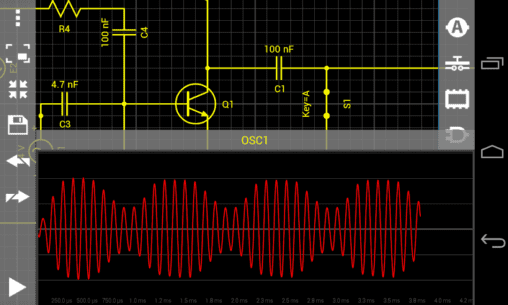
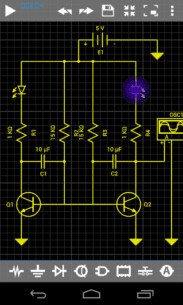
Introducing DroidTesla: Your Go-To Circuit Simulator
DroidTesla is a simple yet powerful circuit simulator designed for various users, from students new to electronics circuit design to seasoned professionals seeking a quick and handy tool for circuit design calculations.
Unlike traditional SPICE tools for PC, such as Multisim, LTspice, OrCad, or PSpice (trademarks belong to their respective owners), DroidTesla offers interactivity and innovation that enhances the learning experience.
Core Functionality
DroidTesla simulates basic resistive circuits using Kirchoff’s Current Law (KCL). The simulator systematically forms a matrix based on KCL and solves for unknown quantities using various algebraic techniques, including:
Gaussian eliminationSparse matrix techniques
Handling Non-Linear Components
For non-linear components like diodes and BJTs, DroidTesla employs an iterative process to find approximate solutions. It begins with an initial guess and refines the solution through successive calculations. The Newton-Raphson iterative algorithm is utilized for circuits with non-linear I/V relationships.
Reactive Elements Simulation
When it comes to reactive elements such as capacitors and inductors, DroidTesla uses numeric integration methods to approximate their state over time. The simulator currently offers:
- Trapezoidal integration (with plans to add the Gear method later)
While both methods yield similar results for most circuits, the Gear method is generally considered more stable, whereas the trapezoidal method is faster and more accurate.
Supported Components
DroidTesla can simulate a wide range of components, including:
- Resistor
- Capacitor
- Inductor
- Potentiometer
- Light Bulb
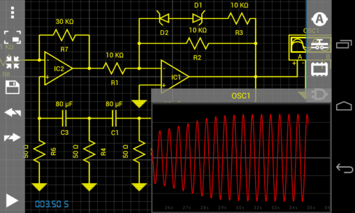
- Ideal operational amplifier
- Bipolar junction transistor (NPN, PNP)
- MOSFET (N-channel depletion, N-channel enhancement, P-channel depletion, P-channel enhancement)
- JFET (N and P)
- PN Diode
- PN LED diode
- PN Zener diode
- AC and DC current sources
- AC and DC voltage sources
- Current and voltage controlled sources (CCVS, CCCS, VCVS, VCCS)
- Square and triangle wave voltage sources
- AC and DC ammeters
- AC and DC voltmeters
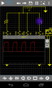
- Two-channel oscilloscope
- SPST and SPDT switches
- Voltage and current controlled switches
- Logic gates (AND, NAND, OR, NOR, NOT, XOR, XNOR)
- JK flip-flop
- 7 Segment Display
- D flip-flop
- Relay
- IC 555
- Transformer
- Graetz Circuit
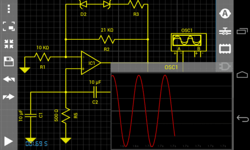
Tips for Oscillator Design
If you are designing oscillators, remember to set a small initial value on some of the reactive elements. Check the examples for guidance.
What's news
UI improvements
Download Droid Tesla Pro
Download the paid installation file of the program with a direct link - 36 MB
.apk


 2.5.2 Apk for Android 9")
 2.9.5 Apk for Android 10")
 1.4.19.b Apk for Android 11")

 13.8.0 Apk for Android 13")
 1.13.4 Apk for Android 14")
 2.9 Apk for Android 15")


